End-of-life stage. Condition Monitoring
As a power transformer approaches the End of Life stage, the implementation of condition monitoring techniques will become more important and critical, as the probability of failure increases.
We will try to see, in this item, the condition monitoring techniques that best fit for this stage in the transformer life cycle.
Below is table No. 2, with the most common and effective diagnostic techniques to detect the characteristic problems of the End of Life stage of the transformer.
Table N° 2
| Component | Diagnostic technique | Effectiveness of the technique |
| Winding(Insulation) | CGD with a preponderance of CO and CO gases2, next to H2. Furans | Well established. Reliable in determining the failure mechanism. |
| Internal connections | CGD with H gas activity2 and C2H2 (arches). Acoustic PD detection. | Well established. |
| Magnetic core | CGD. Analysis of fuel gas patterns. Transformer temperature control and evaluation. Core insulation resistance test. Acoustic PD detection. | Well established. Reliable in determining the failure mechanism. |
| Core and windings | Acoustic noise detection at 50 Hz. FRA test. | Well established. |
| Oil Bushings | Visual inspection for contamination. Visual inspection for losses. Visual inspection for structural damage. Oil level control. Infrared thermography. TD and PC test. | Well established. Reliable and effective. |
| Oil-free bushings | Visual inspection for contamination. Visual inspection for structural damage. TD and PC test. | Well established. Reliable and effective. |
| Expansion Tank | Moisture and air detection. Visual inspection. | Well established. Reliable and effective. |
| Cuba | Visual inspection. | Easy to detect |
Condition analysis with combustible gases
As we have already discussed, CGD is the most important and effective diagnostic technique for determining the condition of a power transformer.
It allows us to detect a variety of problems, including:
- Deterioration of solid insulation.
- Localized overheating.
- Overheating in conductive parts.
- Overheating of the magnetic core.
- Low energy discharges.
- High-energy discharges.
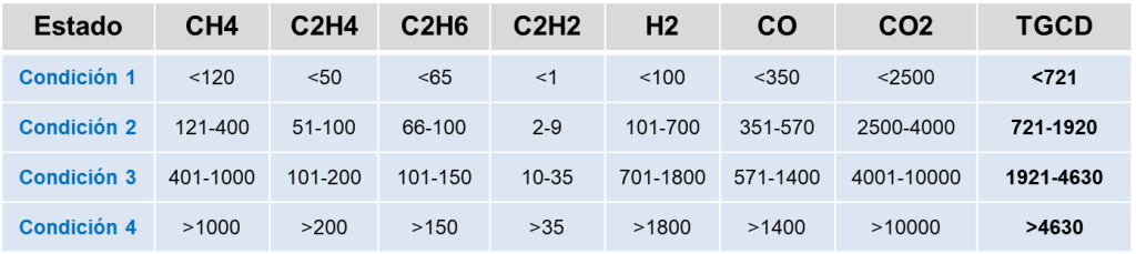
A reference for the analysis of combustible gases is to determine in the first instance the condition of the transformer in the event of a possible state of failure.
Table No. 3 shows this reference (the unit of each gas is ppm), which, in the first instance, will be the one that confirms or endorses the existence of a state of failure
Table N° 3
Terms Reference:
Table N° 4
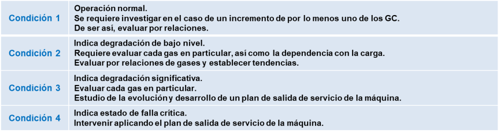
Each condition represents, in greater detail, the following:
- Condition 1 = The TGCD level of this condition (< 721 ppm) is an indicator of a normal and safe condition of the transformer. In the event that some of the levels of the combustible gases exceed the value specified in Table No. 3, a more exhaustive evaluation should be carried out.
- Condition 2 = The TGCD level (> 721 ppm and < 1920 ppm), for this condition, is an indicator of an incipient or probable state of failure. It requires a particular evaluation of each fuel gas, in relation to the level and speed of generation and the eventual dependence on the state of load of the transformer. It should be complemented with the evaluation of gas ratios and comparative analysis.
- Condition 3 = The TGCD level (> 1921 ppm and < 4630 ppm) is an indicator of an advanced state of oil and/or paper degradation. It requires a particular evaluation of each fuel gas, in relation to the level and rate of generation, as well as the evaluation of gas ratios and comparative analysis. A plan for the eventual out-of-service of the transformer must be foreseen for its intervention.
- Condition 4 = The TGCD level (> 4630 ppm) is an indicator of a critical failure state, associated with advanced degradation of the oil and/or paper. The transformer must be intervened in the short term before reaching the state of catastrophic failure.
It is noted that the total amount of dissolved fuel gases (TGCD) does not incorporate the CO gas2.
After a possible failure condition has been defined, the next step will be to validate this status.
To this end, the growth rates of the gases are analyzed, as indicated in the following table.
Table N° 5
| Gas | L1(ppm) | G1(ppm/month) | G2(ppm/month) |
| H2 | 100 | 10 | 50 |
| CH4 | 75 | 8 | 38 |
| C2H2 | 3 | 3 | 3 |
| C2H4 | 75 | 8 | 38 |
| C2H6 | 75 | 8 | 38 |
| CO | 700 | 70 | 350 |
| CO2 | 7000 | 700 | 3500 |
L1, determines the limit from which stricter monitoring of the transformer must be adopted. This is because it is very possible that an internal failure process is effectively developing.
G1 determines a limit for the monthly generation rate of each fuel gas. It establishes the existence of a failure process in development, forcing the adoption of deferred corrective actions.
G2 determines the monthly gas generation speed limit, from which the critical state of the transformer must be established. It requires immediate corrective action.
Once the fault state has been confirmed, the contents of the gases will be analyzed at the absolute and ratio levels, in order to determine the cause of the problem.
To this end, the different methods of analysis of dissolved fuel gases in oil are used (See the articles “Fault Gases in Transformers, Part 1 and Part 2”).
Furan Assay
When cellulose decomposes, it releases, in addition to CO and CO gases,2, chemical compounds soluble in oil, called furans.
Of all these compounds, the most significant for assessing the degradation status of cellulose is 2-furfuraldehyde (2-FAL).
A normal reference value for a power transformer is a quantity of furans, dissolved in the oil, in the order of < 0.1 ppm.
This level is a key indicator of the degradation of the insulating paper of windings, so the test becomes a fundamental tool in the monitoring of the condition status of the transformer in the End of Life stage.
Core insulation strength test
The grounding of the magnetic core must be unique, since otherwise it favors its overheating, due to the circulation of eddy currents.
An effective technique to evaluate this condition is through the measurement of the insulation resistance of the core, after disconnecting its grounding.
If it is of low value, it is an indicator of the existence of multiple earthing, so corrective actions must be taken, in order to eliminate these additional lands.
The overheating of the magnetic core, derived from this problem, will also be the cause of the overheating of the oil and the effect on the insulation of the windings.
FRA Trial
The Frequency Response Analysis assay is a very effective diagnostic technique to detect problems derived from mismatches in the windings and the magnetic core.
This test is based on obtaining the characteristic of the frequency response of the transformer, which can be represented by a circuit with inductive and capacitive coupling, in the face of different excitations of low voltage sine waves, in a given frequency range.
Any modification of the circuit parameters, as a result of mismatches and/or displacements of the windings/core, may be detected from the frequency response records.
It is a comparative base test, so an initial reference is required, in order to evaluate the characteristics obtained.
If you need to perform complex assays such as FRA or CGD, contact NOVA MIRON for diagnostic services.
Delta Tangent and Capacity Testing
This test allows the dielectric losses of an insulation to be measured. The degradation over time of any insulation will lead to a consequent increase in these losses.
The delta tangent is an indirect indicator of dielectric losses, representing a very low value, for insulation in good conditions.
In addition, it should be taken into account that the variations of this parameter must be very small, over time, for a power transformer.
In this sense, it represents a key indicator to evaluate the state of the condition of the transformer in the End of Life stage.
Acoustic test of partial discharges
The acoustic signal is the medium through which high-energy (arcing) and low-energy (partial discharge) discharge activities can be detected.
The acoustic waves propagate through the oil, from the source of generation of the discharges and will be detected on the external surface of the tank, through sensors specially located in it.
Problems arising from misalignments of the mechanical fastening system, as well as erosion or cracking of the solid insulation, characteristic of the End of Life stage of the transformer, can be monitored with this technique.
Deepening Readings
- Management Strategy: These diagnostic techniques are essential for the End-of-Life Management of assets.
- Failure Mechanisms: For a detailed description of the faults detected by the CGD, see Failure and Maintenance Mechanisms.
