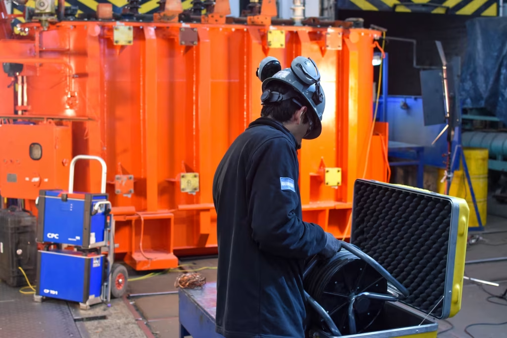
The electrodynamic stresses that take place inside transformers, specifically in the primary and secondary windings, are of vital importance at all stages of their life cycle.
This fact is justified by the growing increase in the short-circuit capacities of modern Electric Power Systems (SEP), associated with the increase in generation levels in the nodes of the grid and the interconnections implemented, both locally and internationally.
In this sense, the specifications, design and manufacture of the pre-commissioning stage and the operational contexts, both in the expected life stage and in the end-of-life stage, will be fundamental factors to ensure an adequate capacity of the transformer to withstand the short-circuit conditions of the grid.
Electrodynamic stresses, derived from short-circuit currents, are the cause of eventual mechanical and electrical failure processes.
Among the former we can find deformations and collapse/rupture of the transformer windings and among the latter those that are indirectly related to mechanical windings, mainly due to damage to the insulation.
In turn, the circulation of short-circuit currents in the transformer will cause damage to the bushings and the tank, as well as a possible risk of fire in the installation.
In this sense, we will proceed, firstly, to make a brief description of the type of short-circuit currents that can be established in a SEP, in the event of a fault state and the incidence of these depending on the type of transformer.
Then, we will go on to explain the types of electrodynamic stresses that take place inside the transformer, when the short-circuit current circulates.
We will also evaluate the effects or problems caused by them, mainly the action of the stresses on the windings.
We will continue with an introduction to the topic of the dynamic behavior of the stresses on the windings, as well as the consequences of this physical process.
Finally, we will see how all these problems influence the different stages of the transformer life cycle, especially those related to the specification, design and manufacture of the transformer.
In order to expose all these issues, this work has been divided into the following parts:
Types of faults and short-circuit currents
In this item we are going to determine the basis for the calculation of the short-circuit currents that can manifest in a SEP. Specifically, we are going to focus on just two of the possible types of faults that can be established in the installation.
For these purposes, we will follow the definitions and guidelines specified in the IEC 60909 (Short-circuit currents in three-phase a.c. systems) standard.
This standard defines a short circuit as the accidental or intentional conductive connection, through a path of relatively low resistance or impedance, between two or more points of a circuit, which are usually at different potentials.
The possible short-circuit currents that can be established in an SEP are associated with the following types of faults:
a) Three-phase failure.
b) Biphasic failure.
c) Monopolar to neutral fault (phase and neutral conductor),
d) Monopolar fault to PE (phase conductor and PE).
e) Biphasic ground fault.
f) Double single-phase fault to earth.
g) Single-phase ground fault.

Figure 1 details the conductive characteristics for each type of fault, as well as the designation, indicated by IEC 60909, for each associated current.
For the sake of simplicity, we highlight the most common failures below.

It should be borne in mind that the three-phase short circuit is symmetrical, so for the purposes of the calculations it will only be sufficient to resort to a simple direct sequence circuit.
In general, biphasic is characterized by developing a current of magnitude lower than three-phase.
The single-phase short circuit to ground also meets this condition, with the exception of having the case of a transformer with YNd connection, also incorporating an internal triangle winding.
It can also be verified that the magnitude of the single-phase short-circuit current to ground is greater than the corresponding three-phase one, when the Z0/Zd ratio < 1 is met, with Z0 being the homopolar impedance and Zd being the direct sequence impedance of the system.
In view of the above, in general, the three-phase short circuit will be the one with the highest intensity and consequently the one that may eventually cause the greatest damage to the transformer. In this sense, it will be sufficient for the design of the transformer to have the capacity to support it.
As we have already mentioned, there are exceptions to this case, one of them corresponding to a transformer with a YNd connection and an internal winding connected in a triangle.
For this type of transformer, the single-phase fault current to ground will be the one with the highest intensity.
Therefore, the short-circuit design of this machine should be based on the type of fault indicated.
In this sense, it will be more effective to address only the calculations and effects of three-phase and single-phase short-circuit currents to ground, through the method of network sequence circuits.
Without going into the basics of this method, the sequence circuits for each symmetrical component are detailed below, i.e.: Direct (or Positive), Inverse (or Negative) and Homopolar (or Zero), seen from the point of failure F.


The reactances (resistive components are disregarded) of the generator, transformer and transmission line, for each of the sequences, are highlighted, denoting with “1” the direct one, with “2” in reverse and with “0” in the homopolar one.
Based on these sequence circuits, the levels of short-circuit currents can be determined, depending on each type of fault and the consequent interconnection of the same.
In this way, the calculation of the short-circuit currents for the types of faults already indicated as main in the analysis of the electrodynamic stresses on the transformers is detailed below.
A) Three-phase failure
As we have already mentioned, this fault is symmetrical (assuming balance in the three phases), so the equivalent circuit, depending on the corresponding sequences, will be:

The factor “c” is called the Voltage Factor and is specified in the standard with the following values, depending on the nominal voltage of the network.
| Nominal mains voltage (A) | Cmax | Cmin |
| 100 to 1000 V | 1,05 | 0,95 |
| >1 kV to 35 kV | 1,10 | 1,00 |
| >35 kV | 1,10 | 1,00 |
Cmax = for the calculation of the highest short-circuit current.
cmin = for the calculation of the lowest short-circuit current.
The edge conditions at the point of failure, taking into account the scheme, will be:
UL1 = UL2 = UL3 = 0
IL1 + IL2 + IL3 = 0
Therefore:

By applying the reverse transformation of symmetrical components, the value, in magnitude, of the three-phase short-circuit current at the point of failure is obtained.

B) Single-phase grounded
In this case, the equivalent circuit for the calculation of this current will be:
Figure 5

Now, the edge conditions at the point of failure will be:
UL1 = 0
IL2 = IL3 = 0
IL1 = I”k1
Then:
I1 = I2 = I0

Zs = Z1 + Z2 + Z0
By applying the reverse transformation of symmetrical components, the value, in magnitude, of the single-phase short-circuit current to ground at the point of failure is obtained.

It is important to note that the value of this current will be fundamentally determined by the characteristic of the homopolar sequence circuit.
In other words, this determining characteristic will be associated with the type of connection of the transformer, since depending on the internal configuration of the windings, as well as the type of grounding of the center of the star, the value of the Z0 will acquire specific values in the calculation.
Very important to take into account is the behavior over time of the short-circuit current. For these purposes, two classes can be established, namely:
a) Short circuit far from the generator
In this case, the following relationships are verified.

The characteristic in time of this current will be:
Figure N° 6

b) Short circuit near the generator
The following relationships are now fulfilled:

With the characteristic indicated in the following figure.

In this case, the subtransient and transient characteristics of the synchronous generator will be decisive in the establishment of the short-circuit current.
It has:
– InG = nominal current of the generator.
– I”k = symmetric initial short-circuit current.
– IP = Peak short-circuit current.
– iDC = aperiodic decay current.
– A = initial value of the aperiodic component.
– Ik = short-circuit current in steady state.
Types of electrodynamic stresses
The forces that are established inside the transformer (windings) are a consequence of the interaction of the magnetic field associated with the dispersion flux and the current that will circulate through the winding.
The base expression for the calculation of these stresses (forces) will be the following vector relationship,
F = i L × B.
Where “i” is the current flowing through the winding, L is the total length of the winding, B is the magnetic field of dispersion, and F is the force that is established on the winding.
Since the magnetic field of scattering depends directly proportionally on the current flowing through the winding (B(i) ~ i), then it follows from the previous relation that the magnitude of the force will be directly proportional to the square of the current (F ~ i2).
Under nominal operating conditions, the transformer must be designed to be able to withstand these stresses, but it must also be designed to be able to withstand the stresses that are established in the short-circuit states.
Based on what is indicated in item 2 and taking into account the functional dependence of the force on the current, in the following figure we can observe the characteristics over time of both quantities.

In it, the short-circuit current in time is observed, with its alternating and decaying component. The “ip” value is highlighted, corresponding, as we have already seen, to the maximum reached by this current.
It is therefore concluded that, when a short-circuit current circulates through the windings, in the event of a possible state of failure, the forces generated will be of appreciable value, determining the establishment of electrodynamic stresses of significant magnitude.
En la figura inferior se destaca la característica temporal de la fuerza (F ~ i2) que se desarrolla en los bobinados, como consecuencia de la circulación de la corriente de cortocircuito. También se observa el máximo que alcanza la fuerza (Fp), valor asociado a la corriente ip.
Muy importante es considerar las componentes de F(t). Tendremos 4 en total, a saber:
– Dos componentes de alterna. Una a frecuencia de red con un decaimiento en el tiempo y la otra a doble frecuencia de red, con un valor constante pero pequeño.
– Dos componentes unidireccionales. Una de valor constante y la otra con decaimiento en el tiempo.
Teniendo en cuenta la naturaleza vectorial de la fuerza F, a los fines del estudio de los esfuerzos y sus efectos, es conveniente evaluarlos en relación a sus componentes en el espacio.
A estos fines, se establecen las componentes Axial y Radial de la citada fuerza (F = Fax + Frad).
En el siguiente esquema, podemos observar cómo se despliega la fuerza F resultante, punto a punto, en el interior de los bobinados, así como las correspondientes componentes ya citadas.

En la figura se observa una ventana del núcleo magnético de un transformador, con el bobinado interno en BT y el externo de AT.
También se observan las líneas del campo de dispersión, así como la fuerza F en distintos puntos de los bobinados. Como ya comentamos, esta fuerza se representa, por convención, a través de las componentes radial (Frad) y axial (Fax).
El campo de dispersión radial tendrá la dirección en el eje “x”, dado por el valor Bx y el campo de dispersión axial en el eje “y”, con un valor dado por By.
A los fines del estudio de los efectos de los esfuerzos radial y axial sobre los bobinados, será conveniente tener en cuenta cómo se constituye la estructura magnética-mecánica en la ventana del núcleo del transformador. Tendremos:
Φr → Br ≡ Bx → Fax (axial component).
Φa → Ba ≡ By → Frad (radial component).
Being:
Φr = radial dispersion flux.
Φa = axial dispersion flow.
Effects of stresses and thermal resistance to short circuit
Based on what has been seen in item 3 of Part 1, electrodynamic stresses can be represented through 2 components, one in a radial direction and the other in an axial direction, in reference to the windings of AT and BT, housed in each column of the magnetic core.
The action of the force F on each winding, as well as the radial and axial components, can be seen in the following figure.
Figure 1

As we have already highlighted in item 3 of Part 1, the figure represents a window of the transformer’s magnetic core, with the LV winding housed in the inner part and the HV winding on the outside.
During the circulation of a short-circuit current over the windings, a high concentration of the magnetic flux density will be established in the air window of the core.
Under these circumstances, the scattering fields of each adjacent column of the nucleus will magnetically influence the others.
As a result, a higher interaction force is generally obtained in the windings that make up the central column of the transformer core.
It is important to note that there is a variety of methods that allow calculating the stresses on the windings, before circulating states of short-circuit currents (e.g. Roth’s method).
Nowadays, the numerical method of Finite Elements has been introduced, which models the transformer as an asymmetrical and non-linear electromagnetic device, in the three spatial dimensions (3D modeling).
With the aforementioned method, high-precision results can be obtained, which allow the magnetic-mechanical phenomenon to be studied in depth, both inside and outside the nucleus window.
For practical purposes and understanding of this process, it will be sufficient to adopt an analytical model in two dimensions (2D) and with a set of hypotheses, which will facilitate the development.
2D analytical model hypothesis:
- The magnetic core adopted will be 3 columns and with infinite magnetic permeability (zero reluctance).
- It is assumed that the configuration of the windings in HV and LV are cylindrical and concentric in characteristics.
- The heights of both windings are considered to be equal.
- The effects of the scattering magnetic field at the upper and lower ends of the core columns are neglected.
- In a short-circuit state, a large concentration of the scattering field is established in the windows of the magnetic core, assuming that it will be in this where practically all the fault mechanisms associated with the stresses will develop.
In Figure N° 2 we can see the basic structure of the windings and magnetic core that we will use in the analysis of the stresses.
Figure N° 2

Being:
Lm1 = mean length of the external winding (AT).
Lm2 = mean length of the internal winding (BT).
Lm0 = average length of the dispersion channel.
d1 = width of the external winding.
d2 = width of the internal winding.
d0 = width of the dispersion channel.
The analysis is summarized in verifying the mechanical capacity of the windings to be able to resist the peak of electrodynamic force (Fp) in a short-circuit state (see Part 1, item 3).
The different stresses that can be developed in the windings, as well as the associated effects on their structure, will be explained below.
Radial Force
As we have already seen, radial forces are caused by the scattering axial magnetic field (Φa → Ba ≡ By → Frad = radial component).
From Figure 1 it can be seen that the inner winding (that of BT) is subjected, radially, to a compressive stress, which tries to compress it towards the column of the magnetic core.
On the other hand, the external winding (AT) is subjected to a radial tensile stress, so it will tend to move outside the structure.
It is also observed, in Figure 1, that the maximum radial force will be established in the middle zone of the windings, where the radial component of the dispersion field is minimized.
In order to evaluate the magnitude of the radial force, we must consider the distribution of the Magnetomotive Force in the structure of the windings.
This distribution acquires a trapezoidal characteristic, taking into account the fact that the levels of magnetomotor forces, both on the inner side of the internal winding and on the external face of the external winding, are of zero value.
The distribution is linear in both windings, increasing from zero to the corresponding maximum in each winding, i.e. N1I1 in the external (AT) and N2I2 in the internal (BT).
In the scattering channel, the magnetomotive force is maintained, along the channel, with the constant value of F1 = F2.
In Figure 3 we can see the structure of the core-windings, as well as the trapezoidal distribution of the FMM.
Figure N° 3

Being:
D1 = mean diameter of the external winding (AT).
D2 = average diameter of the internal winding (BT).
D0 = average diameter of the dispersion channel.
d1 = width of the external winding.
d2 = width of the internal winding.
d0 = width of the dispersion channel.
ha = height of the windings.
F1 = N1 I1 = fuerza magnetomotriz máxima en el arrollamiento externo (AT).
F2 = N2 I2 = fuerza magnetomotriz máxima en el arrollamiento interno (BT).
En las condiciones ideales, planteadas en las hipótesis, se tendrá que: F1 = F2 = Fm.
A partir de la configuración de la FMM se puede obtener el valor máximo del campo magnético de dispersión en el espacio de aire entre los dos arrollamientos (d0). Tendremos:
B0m= 20 Fmha
A continuación, veremos los dos casos de fuerzas radiales que se pueden establecer en los arrollamientos.
- Fuerza radial de tracción
Como ya hemos comentado, el arrollamiento externo de AT será el que se encontrará sometido a un esfuerzo radial de tracción, cuyo efecto será el de traccionarlo hacia afuera de la estructura. A este esfuerzo resultante también se lo denomina “hoop stress”.
Teniendo en cuenta la distribución trapezoidal de la FMM, sabemos que el campo de dispersión incrementa su valor desde cero en la cara externa del arrollamiento (De), hasta su valor máximo Fm en el diámetro interior (Di).
Figura N° 4

Siendo:
Di = diámetro interior del arrollamiento externo (AT).
De = diámetro exterior del arrollamiento externo (AT).
Dm = diámetro medio del arrollamiento externo (AT).
Frad = fuerza radial neta sobre el arrollamiento externo (AT).
Operando, se puede obtener la siguiente expresión de la fuerza media por unidad de área transversal de cada vuelta del arrollamiento, expresada en N/m2.
σm= 02πρha k2PfZ°/12
en donde:
ρ = resistividad del material conductor del arrollamiento a 75 °C.
k = factor de asimetría de la corriente de cortocircuito, considerando la componente unidireccional.
Pf = pérdidas en el material conductor del arrollamiento (cobre o aluminio) por columna del transformador.
Z°/1 = impedancia en tanto por uno del transformador.
ha = altura del arrollamiento.
Para este arrollamiento, los conductores cercanos al canal de dispersión (en Di), estarán sometidos a las máximas fuerzas radiales, mientras que aquellos ubicados en la parte externa (en De) el efecto será prácticamente nulo.
Debemos destacar que, en base a lo visto en relación a la distribución de la FMM, la fuerza se distribuye linealmente entre ambas caras del arrollamiento, desde un valor máximo en la cara interior hasta un valor nulo en la exterior.
En tal sentido, se asume que la carga mecánica sobre los conductores más exigidos (ubicados en la cara interna) se transmite a los conductores menos exigidos (ubicados en la cara externa).
Por lo tanto, el cálculo de “σm” tiene en cuenta el promedio de la fuerza a lo largo de la profundidad radial del arrollamiento, atendiendo al hecho de que la carga mecánica se comparte en manera uniforme. Ver en la figura N° 4 el esquema de distribución uniforme de la fuerza en ambas mitades del bobinado, como equivalente a actuar sobre el diámetro Dm del mismo.
Al excederse la resistencia mecánica del conductor, el esfuerzo radial llevará a la deformación del bobinado, con el resultado de provocar fundamentalmente un daño en la aislación.
La ruptura del bobinado, como consecuencia de este tipo de esfuerzo, puede estar directamente asociada con un mal proceso de conformado de los conductores del mismo, en la etapa de fabricación del transformador.
- Fuerza radial de compresión
Este esfuerzo se establece en el arrollamiento interno, en donde la máxima fuerza se asienta en la cara externa y la mínima en la cara interna, con el resultado neto de una presión de compresión a lo largo de la circunferencia del citado bobinado.
Pueden presentarse dos casos, a saber:
b.1) Por pandeo forzado
En este caso, la deformación del bobinado ocurre cuando los esfuerzos de compresión resultantes, exceden el límite elástico de los conductores en la parte externa, mientras que en la cara interna del bobinado existe una rigidez significativa, debido a la estructura de los soportes.
Figura N° 5

En la figura N° 5 se observa la fuerza radial de compresión (Frad) actuando sobre la circunferencia externa del arrollamiento interior y la fuerza de reacción que ejercen los separadores axiales (Fs).
También se observa la deformación característica que ocasiona este esfuerzo, estableciendo un pandeo entre los separadores axiales que conforman el sistema de soporte, a lo largo de toda la circunferencia del bobinado.
En este caso, la rigidez que presenta el sistema de soporte es superior a la correspondiente de los conductores. Se asume que la rigidez se incrementa si los separadores se encuentran soportados por el núcleo magnético.
b.2) Por pandeo libre
La deformación del bobinado interno tiene su causa en la acción de la fuerza radial de compresión debido a un pandeo sin reacción de los soportes axiales.
Este caso se presenta cuando la rigidez del conductor es mayor a la del cilindro interno que conforma el bobinado y los espaciadores axiales no se encuentran firmemente soportados.
Figura N° 6

De la figura se observa que se establece un abultamiento del bobinado, en uno o varios puntos a lo largo de la circunferencia del arrollamiento. Este abultamiento puede ser hacia afuera o hacia adentro del bobinado.
Algunos de los factores que favorecen este tipo de deformación son, además de la menor rigidez mecánica de la estructura de soporte, en comparación con la del conductor, un deficiente ajuste del bobinado y una eventual excentricidad del mismo.
Sin entrar en los detalles de la demostración, a continuación podemos expresar la relación que permite determinar la fuerza media por unidad de área transversal de cada vuelta del arrollamiento:
σm= E12 e NsDm2Ns2-4Ns2
En donde:
σm = fuerza media por unidad de área transversal de cada vuelta del arrollamiento.
Dm = diámetro medio del arrollamiento interno.
Ns = number of axial separators.
e = conductor thickness.
E = modulus of elasticity of the conductive material,
If we assume that Ns >> 1, then we can obtain the minimum number of axial separators to be installed on the periphery of the winding.
Ns= Dme 12 σmE
Axial force
In this case, the force component in the axial direction will owe its cause to the dispersion flux in the radial direction, according to: Φr → Br ≡ Bx → Fax (axial component).
One of the effects of the action of this effort is that if the winding is not well formed (well adjusted round by turn) there can be an overlap or transfer of turns in the column, thus causing damage to the insulation.
It may also be the case that vibrations occur due to the effect of this axial stress, leading to a process of gradual wear of the insulation due to friction between the conductors and the axial spacers.
It will be important to bear in mind that the inner winding, being closer to the column of the magnetic core, will be the one that will withstand a greater axial compressive force, due to the existence of a higher radial flux density.
Below we will indicate the problems arising from the action of this effort.
- Bending between radial spacers
One of the consequences of axial stress on the winding is to cause a buckling of the conductors between the radial spacers.
Figure 7 shows this effect.
Figure 7

A detail to consider is that the most significant problem will be the consequent damage to the insulation.
It is emphasized that the maximum bending effort on the conductor will have the following value:
= Famx d2 y12 I0
Where:
Famx = maximum axial load per buckling (kg/cm).
d = space between two radial spacers.
y = maximum distance between the neutral axis and a conductor.
I0 = moment of inertia of one turn of the winding (winding disc).
In the design of the winding, it will be taken into account that the value of σmax must be lower than the limit value of the load of the conductive material used.
- Winding Tilt
When the axial compression force exceeds a certain value, given by the mechanical resistance of the conductors and radial spacers, there is an inclination deformation of the conductors that make up the winding discs, in a
characteristic of the “zig-zag” type, as can be seen in Figure 8.
Figure 8

The rotation of the cross-section of the conductors through the perpendicular axis of symmetry is highlighted.
In this situation, there are two components of the force that oppose the inclination of the entire set of conductors.
The first reactive component is the one provided by the conductive material itself and the second is the one associated with the friction between the conductor and the radial spacer.
Considering these two reactive components, the total critical load that can withstand the action of tilting can be expressed by the axial force of compression. It has:
Frc= π N E e a26 R+ Nr N b c e36 a
Being:
Frc = total critical reactive force at the inclination of the conductors.
N = number of winding turns.
e = thickness of the conductor in the radial direction.
a = height of the conductor in the axial direction.
R = average winding radius.
E = modulus of elasticity of the conductor.
Nr = number of radial spacers.
b = width of the radial spacer.
c = constant that depends on the material that makes up the radial spacer.
From the previous expression, two important observations can be deduced. The first refers to the decrease in inclination resistance with the increase in the mean winding radius (R) and the second refers to a decrease in resistance to the use of thin conductors in winding forming.
This type of failure is the cause of damage to the insulation of the conductors, with the consequent problem associated between coils of the winding.
In order to evaluate the thermal behavior of the windings in the face of a circulating state of a short-circuit current, we will take into account that the immediate effect will be to increase their temperature, taking into account the fact that an adiabatic process is established.
Because modern short-circuit protection devices act in times of the order of milliseconds, the harmful effects of the current will not be reflected in the transformer windings.
The thermal limit is determined by the temperature value, from which crystallographic damage is generated in the conductive material. For a copper conductor, the limit value is θmax = 250 °C and for aluminum θmax = 200 °C.
We can analyze a case, adopting the following calculation expression, corresponding to a transformer winding with a copper conductor:
θf= θi+2 (θi+235)106000JnZ°/12t-1
Being:
θf = final temperature reached by the conductor in the short-circuit state (°C).
θi = initial conductor temperature before short circuit (°C).
Jn = nominal current density in the winding (A/mm2).
Z°/1 = transformer short-circuit impedance in per unit.
t = duration of the short circuit (s).
In order to avoid damage to the winding structure, the ratio θf < θmax must be met.
If we adopt an initial conductor temperature in the winding of an oil-filled transformer of 100 °C, and which has a Z = 8 %, with a nominal current density of 3 A/mm2, we will have the value of the final temperature
will be θf = 109 °C, assuming that the protective device acts within 1 s after the short circuit has been established.
As we can see, this value is lower than the maximum limit allowed in copper.
In this sense, it can be concluded that, in general, the thermal integrity of the windings of a transformer is not affected by the circulation of a short-circuit current.
Fundamentals of Electrodynamic Analysis
This analysis is based on two main issues.
The first refers to the mechanical system that makes up the windings, together with their structural fastening supports, thus determining a mass-elasticity-damping set.
The second is based on the oscillatory nature of the electrodynamic force.
Its analytical representation is as follows:
Ft=Fp 12+e-2tT-2e-tTcos ωt+12cos 2ωt
As we had already indicated in item 3 of Part 1, it is made up of two unidirectional components, one constant and the other decreasing over time and two oscillating components, one of network frequency with decreasing amplitude over time and the other of constant amplitude but with double network frequency.
The following figure shows the representation in time of the electrodynamic force.
Figure N° 9

The maximum value of the force (Fp) is associated with the value reached by the peak of the current (ip). This current value will depend on the asymmetry factor (k) of the short-circuit current wave, given by: ip=k 2 I”k.
Therefore, the dynamic analysis in a short-circuit state is fundamentally based on evaluating how this oscillating force in time interacts with the system made up of the conductors of the windings, the insulation and the fastening supports.
All these components introduce the physical parameters of inertia, elasticity and damping into the model.
An important fact to take into account is the dynamic action of the force in the axial direction, since in this case there can be a congruence between the oscillation frequency of the force and the natural oscillation frequency of the system formed by conductor-insulation-supports.
This will be the cause of the establishment of a resonance state, which will lead to large displacements of the windings in the axial direction and therefore to an eventual state of failure of the same.
We should note that in the axial direction, the mechanical system has a greater compression capacity due to the greater amount of insulation along this direction.
A model can be made, through which the dynamic parameters involved in the system can be represented.
Without going into details of the calculation, we can now establish the bases of this model, in which an winding of height “ha” and mass “m” is indicated, under the action of the electrodynamic force F(t) in the axial direction “y(t)”.
Figure 10

The parameters “k” indicated in Figure 10 (not to be confused with the asymmetry factor “k” of the short-circuit current wave) refer to the elasticities of the upper and lower supports of the winding and the parameters “b” to the corresponding mechanical dampings of the same.
Without going into the details of the resolution of this dynamic system, we will say that the results of this must determine the displacement through time “y(t)” of the winding, as well as the natural frequency of the system.
As for the dynamic action on the radial direction, we find that in this direction the conductor offers a greater elastic capacity (k), as well as a lower inertia (m).
Then the natural frequency of the system will generally be much higher than the corresponding excitation frequencies fn ~ km, so in this case we will be far from establishing an eventual state of resonance and a consequent significant amplification of the radial displacement of the winding.
The radial forces are determined through the establishment of a maximum stress, associated with the peak value (Fp) of F(t) and the energy stored by the radial displacement of the winding will be fundamentally elastic.
Let us remember that the objective of the design of the winding-support system will be to obtain a natural frequency of oscillation as close as possible to the excitation frequency given by the F(t), thus avoiding a state of resonance.
Natural frequencies of the mechanical system that are close to 50 Hz (for the first cycles of the force, during the transient process) and 100 Hz (for the steady state of the force) should be avoided.
Impact on the transformer life cycle
We are going to list a set of conditions, to be taken into account in the pre-commissioning stage of the transformer’s life cycle, related to the demands on the short circuit, when establishing the specifications, design and manufacture of the transformer.
From a specification standpoint, we’ll have:
- High short-circuit impedance values for critical transformers.
- High values of neutral grounding impedance, for transmission and distribution systems.
- Take into account the short-circuit levels of the SEP, taking into account the location of the transformer.
- To evaluate the convenience of using a third winding, for stabilization purposes, in transformers with a three-column core. If possible, it should be avoided.
- Evaluate the convenience of using “split” or “divided” type rollovers. If possible, it should be avoided.
- Determine the correct arrangement of the windings, in order to minimise short-circuit stresses.
From the point of view of machine design, we can establish:
- Analyse and evaluate the operating conditions of the transformer in the installation, taking into account the levels and types of short circuits that may occur.
- In order for the winding to be able to resist radial stresses reliably, the dimensions of the conductor must be calculated, taking into account that the conductor will withstand the stress on its own, i.e. without considering the reaction of the supports.
- Adopt lower current density values than conventional ones, in the case of critical transformer windings.
- In the event that it is necessary to incorporate a stabilizing tertiary winding, lower values of the current densities must also be adopted in the design.
- To obtain or estimate the natural frequency of oscillation of the winding-support structure system, in order to avoid the resonance process.
- Use thicker cylinders to contain internal winding.
- Adopt a higher slenderness ratio for the design of the internal winding, in order to increase the resistance to compression, in the face of the action of radial stresses.
- Use, for the forming of the windings, materials with mechanical resistance certified in the manufacturer’s specification sheets and tests.
For the manufacture there will be:
- Implement a rigorous control process in the manufacture and assembly of the windings.
- Acquire the materials that make up the windings from qualified suppliers with certified quality processes in manufacturing.
- Adopt anchoring structures of adequate rigidity and correct attachment to the windings.
- Use, as far as possible, support cylinders for internal winding, with fiberglass material.
- Proceed to a correct and precise positioning of the radial and axial supports.
- Ensure a firm and tight winding of the conductors in the radial direction.
- Avoid burrs on the separators, so that the paper insulation of the conductors is not damaged.
- Ensure correct fastening of the switch and bushing connections.
Conclusions
- The thermal integrity of a transformer’s windings is not affected by the circulation of short-circuit current. Thus, the short-circuit thermal capacity does not represent a determining factor in the design of the transformer.
- It is very important to evaluate the dynamic action of the short-circuit force on the transformer windings, especially in the axial direction. The design of the conductor-insulation-supports system must avoid having a natural frequency of oscillation close to that of excitation, so that a state of resonance is not established.
- Therefore, dynamic analysis is a very important stage in the transformer design phase, as it increases its operational reliability in the face of short-circuit conditions in the installation.
- The failure modes in the external and internal windings due to the action of radial stresses are different. In external winding, the ability to withstand radial stress will depend mainly on the
mechanical tensile strength of the conductive material that makes it up. On the other hand, the resistance of the internal winding to radial stress will depend on the design and configuration of the support system.
- The action of axial stresses can lead to deformation of the windings and anchor structures at the ends of the windings. It should be borne in mind that the anchoring structures at the ends of the windings play a fundamental role in the ability of the windings to withstand axial forces during the short circuit.
- Winding tilt failure, due to the action of axial compression stresses, is one of the most important in power transformers.
For more information on how Novamiron Maintenance Services can protect your transformers against the effects of electrodynamic stresses, visit us at Transformer Maintenance & Services | MIRON and discover how our experience and advanced technology ensure the longevity and reliability of your equipment.
