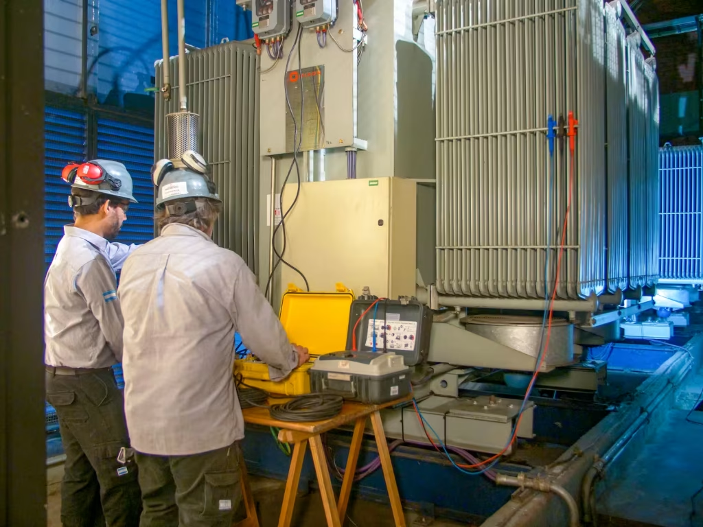
In this item we are going to deal with the expected life of different components of a power transformer.
The expected life, indicated in Table No. 1, establishes the point in time at which the transformer will be able to maintain its functions, with a high degree of certainty.
In the face of poor maintenance, or inadequate interventions, the transformer, upon entering the end-of-life phase with an appreciable level of aging, will begin to increase the probability of the development of a catastrophic failure state.
In this sense, the life expectancy indicator will be key to establishing intervention plans, as well as the appropriate time for the implementation of additional tests and monitoring in Maintenance Management.
In addition, it allows you to outline the Reconditioning Plan or the Replacement/Disposal Plan of the transformer.
We must take into account the following conditions, when formalizing the contents of table N° 1:
- It is assumed that there is correct and reasonable Maintenance Management, carried out through the Expected Life stage of the Life Cycle.
- The appropriate intervention of corrective actions, in the Expected Life stage, that have reestablished the operational condition of the transformer, in the event of detected problems, is also assumed.
- Life expectancy is based on the contribution of specialists, that is, expert knowledge, over evaluations or statistical studies.
- The expected life of the components, indicated in table No. 1, depends strongly on the maintenance activities carried out, as well as on the system events (short circuits in the SEP, overvoltages, etc.).
- Another factor to be highlighted, which negatively influences the expected life, is the operation of the transformer at demands that exceed the nominal design ones. We can highlight, as a main factor of aging, the operation of the machine, in a long time, at an overtemperature regime.
If your management plan requires expert assistance in Maintenance, rely on Maintenance and services for electrical transformers with NOVA MIRON.
Table N° 1
| Expected Life | ||||
| Component | Functional failure | Degradation factor | MP that helps the expected life | Life expectancy |
| Winding(Insulation) | Electrical breakdown | Thermal aging. Pollution. Accelerated aging due to high-temperature operation. | Radiator cleaning. Maintenance of the fans. Verification of the correct flow of cooling air. Verification of the correct operation of the refrigeration pumps. Verification of the PAT of the magnetic core. Transformer operating temperature control. Temperature device calibration. | 30 to 40 years old |
| Internal connections | Deficient design and/or manufacture of the support of the connections. Development of electric roads to the ground potential | Incidence of multiple failures in adjacent equipment or facilities. Failures in the SEP. Failures in the LATs. | No effective maintenance technique. Proceed to repair when the problem is detected. | 20 to 30 years old |
| Magnetic core | Loss of PATs and/or existence of multiple TAPs | Error in core forming and assembly. Vibrations.Loss of insulation between the core and the tank. | Analysis of combustible gases. Core ground assay. Identification and verification of the uniqueness of the PAT. | 40 years |
| Core and windings | Misalignments.Damage to the interlaminar insulation of the core and to the main insulation of the windings | Failures in the installation, in adjacencies to the transformer. Failures in LAT. Vibrations. | Analysis of combustible gases. Analysis of vibrations and acoustic level. | 40 years |
| Oil Bushings | Failure in insulation | External pollution. Internal pollution. Oil loss. Overvoltages. Loss of the leakage line. Factory problems. | Inspection and cleaning. Repair of losses. Replacement due to breakage or damage. | >15 years |
| Oil-free bushings | Failure in insulation | External pollution. Loss of the vanishing line. Factory problems. | Inspection and cleaning. Replacement due to breakage or damage. | >15 years |
| Expansion Tank | Contamination of oil and solid insulation due to failure of tank bag and/or dryer. | Thermal aging of the bag. Silica gel saturation. | Inspection of the bag in transformer shutdowns. Inspection of the condition of the silicagel. | Months (silicagel) 20 years(bag) |
| Cuba | Oil losses due to corrosion and/or gasket wear | Thermal aging of the joints. Cracks in the tank structure due to advanced corrosion status. | Inspection of the condition of the joints. Replacement of the gaskets. Rust removal, treatment and painting of affected parts | 20 years |
The table highlights the detail of the maintenance activities that are recommended to be implemented, in order to increase the expected life of the component.
The predominant degradation factor for each component is also observed.
End-of-life stage. Failure mechanisms
As we have already seen in table No. 1, the critical components of transformers that have already reached the End of Life stage were detailed, along with functional failures (failure mechanisms) and the factors that favor these mechanisms.
Below we will make a description, for each component, of the types of Preventive Maintenance that are required to achieve the attenuation or delay of the associated degradation mechanisms.
In addition, in item 5, the means of detection of these failure mechanisms will be discussed, indicating the appropriate condition monitoring for each case.
Winding Isolation
The degradation of the winding insulating paper takes place between the layers that make up the coils, between the windings themselves and between the phases of the transformer.
The main factor of the degradation of the insulation will be the thermal load, where the overtemperature, acting on a long time, will proceed to accelerate the aging of the cellulose.
Under these conditions it will be important to consider:
- Cleaning radiators will be a critical task, eliminating any possible obstruction to the flow of air cooling. This maintenance tactic will have a great impact on the operational stages of the transformer, during the summer periods.
- Hand in hand with the above, the operational verification of the pumps of the forced cooling circuit, as well as the fans, will be key to maintaining the integrity of the transformer in the face of thermal stresses.
If thermal aging is critical or high-performance equipment is required, consider replacement with power transformers and oil-bath distribution or dry insulation. - A useful technique to detect problems or deficiencies in the cooling system is infrared thermography. It allows you to quickly detect a possible blockage to the cooling air in the radiators.
- Another mechanism of thermal degradation is caused by localized overheating in the transformer, due to internal problems. This factor can develop an accelerated degradation in the insulating paper of the windings, especially in the areas adjacent to the problem.
- The analysis through furan gases will be very effective to determine the level of degradation of cellulose, thus estimating its mechanical resistance to tolerate electrodynamic stresses.
It is important to note that the alteration of the properties of the paper due to the ingress of moisture is not considered a degradation mechanism, from the point of view of the End of Life of the transformer.
Internal connections
The internal transformer connections are the means of interconnection between the windings and the bushings.
These interconnections require a fastening/support system, whose function is to prevent their movement in the event of transient effects (insertion current, short circuit, etc.).
Please note:
- The fastening/support system may be poorly designed and/or manufactured, so it can crack or, failing that, break at an early stage, under electrodynamic stress.
- Over time and in the face of successive failure events, this system will begin to degrade significantly, representing a failure factor characteristic of the End of Life stage of the transformer.
- A characteristic failure mechanism will be the formation of electrical paths that favor the development of discharges to the earth potential.
- There is no direct preventive maintenance technique to determine the deficiency of the clamping/support system. To this end, the best diagnostic technique will be the CGD, thus evaluating the generation of gases due to the activity of partial discharges, which this failure mechanism entails.
- The analysis is complemented with the evaFluation of the fault states that have manifested and recorded in the transformer adjacencies, as well as the electrodynamic events of the SEP.
Missing core PATs or multiple TAPs
The lack or loss of grounding of the transformer’s magnetic core is considered a critical fault state, as it represents the means to avoid discharges from an eventual core potential to the potential of windings.
In turn, the existence of more than one grounding in the core is the cause of favoring the circulation of eddy currents in the volume of the core.
The main effect of this problem will be the overheating of the core directly and the windings indirectly.
Consider:
- The diagnostic technique that allows these problems to be detected is CGD and the degree of severity is measured according to the levels of the combustible gases generated.
- With the transformer out of service, the earth test on the core can be carried out, in order to evaluate the possible loss of the PAT, or the existence of multiple PATs.
- A strong correlation has been established between these problems and electrodynamic fault events. That is, if a high level of electrodynamic events is verified in the vicinity of the transformer site, the greater the probability of PAT problems manifesting.
- PAT problems will also have an associated higher probability of occurrence as the transformer approaches the End of Life stage.
Core misalignments and windings
The adjustment system of the windings and magnetic core can become out of adjustment or eventually break, as a result of the electrodynamic stresses inside the transformer.
A direct effect of this problem will be damage to the insulation of the windings, due to erosion caused by vibration, derived from the misalignment of the mechanical fastening system.
The following will be taken into account:
- The loss of insulation due to erosion or friction will be the main factor to establish a discharge failure event in windings.
- There is no maintenance technique that prevents the clamping system from being out of alignment.
- It will be possible to monitor the level of vibrations or acoustic level (noise) of the machine, which are associated with an eventual loss of the clamping of the windings and/or the magnetic core.
- As a general rule, it should be considered that the greater the number of electrodynamic events recorded in the installation, the greater the probability of misalignments in the winding fastening system and magnetic core.
- As the transformer approaches the End of Life stage, the greater the probability of this problem manifesting, due to the aging of the materials that make up the fastening system and the joint action of electrodynamic events.
Isolation from the Bushings
Bushing failure is usually the cause of severe damage to transformer windings. It can also lead to a catastrophic failure state.
In other words, in order to achieve, or increase, the life expectancy of the transformer, it will be key to control the condition of these components.
For this purpose, two types of bushings are distinguished, those filled with oil and those with solid insulation (or without oil).
Please note:
- The bushings are subjected to external surface discharges, as a result of contamination or loss of the leakage line (porcelain breakage).
- Contamination is due to surface deposition of dust, dirt, etc.
- Loss of the leakage line (e.g., due to breakage of insulation segments), decreases the bushing’s ability to withstand surges.
- The most effective tactics to detect these problems is visual inspection, along with surface cleaning of the bushings, in order to remove contaminants.
- In the areas where transformers are located, where the contamination rate is high (areas with a high level of pollution), a recommended tactic is to carry out a surface treatment on the bushings, through the application of silicone grease, or another compound, which acts as an absorbing agent for the contaminants.
- The insulation of solid bushings degrades over time, with the tangent parameter delta being the most effective for assessing the status of this condition.
Expansion Tank
The transformer must preserve, at all times, its ability to prevent states of overpressure and vacuum, inside the tank.
This is caused by frequent variations in atmospheric pressure.
In this way, the transformers have the expansion tank (with or without a bag), which allows them to absorb variations in atmospheric pressure.
Consider:
- A failure in the expansion tank bag can lead to rapid contamination of the oil and solid insulation with ambient moisture.
- In order to ensure non-contamination with moisture, this system is complemented by an air drying device, the moisture-absorbing agent being silicagel.
- The way to evaluate this problem is through the analysis of the moisture content in the oil, as well as inspecting the condition of the silicagel, on a regular basis. The analysis of the oil over an annual period (under normal transformer conditions) and the condition of the silicagel color through the inspections carried out in the planned rounds.
- When the transformer is out of service, the inspection of the tank bag should be considered as a mandatory preventive maintenance activity.
Cuba
In this case, oil leaks will be the main effect of the resulting problems in the transformer tank.
The following will be taken into account:
- Detection of leaks through the tank seal and other seals, through periodic visual inspection of the planned rounds.
- Oil analysis also provides important information for detecting oil leaks, as well as assessing the consequences.
- Inspection of seams or welds, in order to detect corrosion. In these cases, corrective actions must be taken to eliminate the deposition of oxides on the tank (removal, treatment and painting).
Oil leaks will develop through welds, if early action was not taken on corrosive effects.
Deep Readings (Internal Links)
- Management Strategy: This analysis complements our Transformer End of Life Management Guide.
- Detection Techniques: For techniques for detecting these faults, see our report on Advanced Diagnostics: CGD, Furans and FRA.
