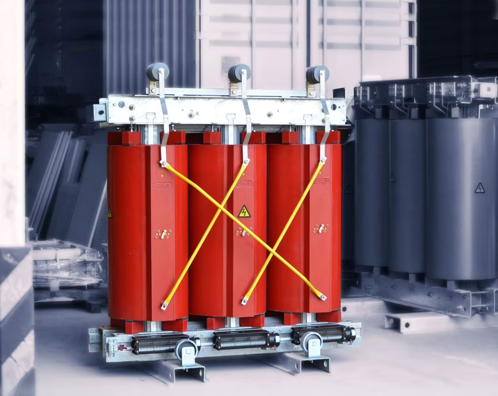
In transformer rooms, which are equipped with power transformers, good ventilation of the chamber must be ensured in order not to allow the heat generated, as a result of the losses of the equipment themselves, to increase the ambient temperature of the room and this increase prevents the development of the maximum power of the transformer.
To ensure proper ventilation of the room, ambient air inlet and outlet channels must be provided, locating the air inlet (cold air) in the lower part of the room (below the transformer level) and the air outlet on the opposite side of the room and being above the transformer level (as close to the ceiling as possible).
These ventilation inlets and outlets must have a sufficient passage section to allow adequate air exchange.
To size these air inlets and outlets, the following guidelines must be followed.
Table of Contents
Natural Convection
Whenever possible, the air inlets and outlets should be sized by natural convection. This method is based on the reduction of the specific weight of the air, as a result of the increase in its temperature, as a result of the absorption of the heat generated by an energy source, in this case the losses present in the power transformer.

(Figure 1)
Having the openings for air inlet/egress, arranged as in Figure 1, the air outlet section can be calculated using the following equation:
Ss = 0.22 x Pt√H (m2) (Ec.1)
Where:
- Ss: Ventilation air outlet section {m2}
- Pt: Total losses to be dissipated (sum of transformer losses in idle and short circuit at 75°C) {kW}.
- H : Distance between half the height of the transformer and half of the upper grid {m}.
The above equation (Eq. 1) is used for an average increase in ambient temperature of 13°C.
For calculations where ambient temperature requires other considerations, the following equation should be used:
Ss = 10.4 x PtH x (tf-ti)3/2 (m2) (Eccl. 2)
Where:
- tf: maximum permissible temperature for hot air {°C}
- ti: average daily expected ambient temperature {°C}.
Because cold air is denser and therefore occupies less volume than hot air, the air intake grille may be smaller than the outlet grille. For adequate ventilation of the room, it should be considered that the ratio between the air intake and outlet section should not be greater than:
Ss = 1.10 x Se (Eccl. 3)
Where:
- Ss: Air outlet section {m2}.
- Se: Air inlet section {m2}.
Forced ventilation

(Figure 2)
When natural ventilation of the room is not possible, room ventilation by means of hot air extraction should be used.
In these applications, it must be considered that all the heat delivered by the equipment must be evacuated by the air extractor(s). They should be located in the upper area of the environment (see figure 2).
Next, it is determined how to proceed to calculate the air flow (Qa), which we will need to evacuate with the extractors.
Starting from the value of the specific heat of the air under normal conditions of pressure and temperature. It can be shown that one cubic meter of air absorbs one kW/°C of temperature increase per second.
So, with this figure, we can calculate the air flow necessary for the proper ventilation of the room.
In general, we will have:
Qa = Pt1.16 x ∆T (m3/s) (Ecl.4)
Qa = 51.7 x Pt∆T (m3/min.) (Eccl.5)
Where:
- Qa: Air flow to be extracted {m3}.
- Pt: total transformer dissipation losses {kW}
- ΔT: permissible increase in ambient air temperature {°C}.
The maximum recommended ambient temperature increase is 20°C; however, for better ventilation of the room, 15°C is usually used.
With this value of 15°C, equations 4 and 5 take the following values:
Qa = Pt17.4 (m3(/s) (Ec.6)
Qa = 3.45 x Pt (m3/min) (Ec.7)
By using equations 4 to 7, it is possible to determine what should be the flow of air necessary to extract from the transformation room, so that the ambient air temperature is maintained within the range of permitted values, thus allowing the transformer to develop its maximum power.
Maximize efficiency with dry-isolation transformers
The choice of insulating materials and the right thermal class, such as the popular F-class or the robust H-class, are critical to ensuring the durability and efficiency of transformers, especially in environments with space constraints or high load demands. Dry insulation transformers stand out for their compact design, high thermal resistance and ability to operate in demanding conditions, prolonging their service life even in the presence of harmonics or extreme temperatures. To find customized solutions that optimize the performance and sustainability of your projects, discover Miron’s dry insulation transformers and quote the best option for your needs.
